Week 9
5/27 - 6/3
Week 8
5/20 - 5/27
Week 7


Figure 12: This shows a top down view of the prototype, this are will be what is shown when the device is worn on the top of the hand.

Week 6


5/6 - 5/13
Week 5
4/29 - 5/6
Week 4

4/15 - 4-22
Week 2
Outside of the lab this week, prior to class the group worked on the presentation aspect of the project. Using the template that our professor, Dr. Fred Allen, provided us the group was able to finish the presentation within the parameters specified. Then the group looked over the presentation as a practice technique for the mock presentation during the week nine lab.
In the lab, the group finished the CAD drawings of the circuit. This can be seen in Figures 13 and 14. This shows two different views of the circuit that is used to run the whole device. Also, in the lab we did the mock presentation. This was a practice opportunity for us to get ready for the final and very important presentation.
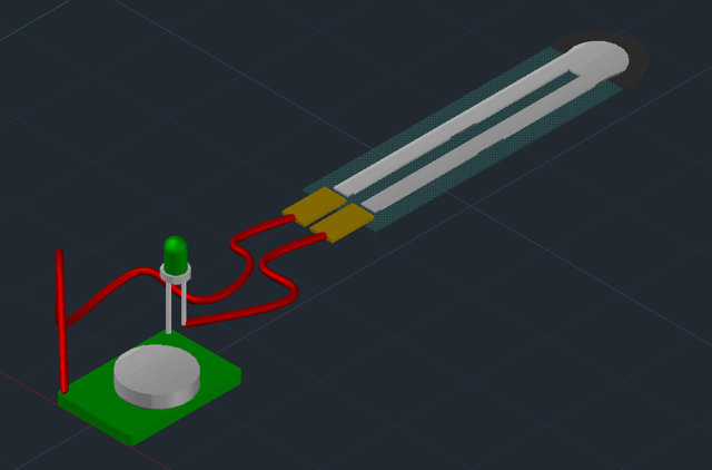
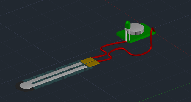
Figure 13: This image shows the CAD of the circuit looking at it from the end of the touch sensor.In the lab, the group finished the CAD drawings of the circuit. This can be seen in Figures 13 and 14. This shows two different views of the circuit that is used to run the whole device. Also, in the lab we did the mock presentation. This was a practice opportunity for us to get ready for the final and very important presentation.
Figure 14: This image shows the CAD model of the circuit looking at it from the 3V battery pack.
5/27 - 6/3
Week 8
This week outside of the lab, we met up and checked the progress of how everyones set tasks were going. We were all on track to be able to finish in a timely manner.
Inside of the lab, the group continued to work on their respective sections. We however, ran into an issue with the prototype. The wire connections and soldering was beginning to wear off, and the connections were not working well. This led to us having to fix this issue quickly. We then started soldering to fix the connectivity issues. The issue was resolved, however, it is something that we are going to continually make sure that it is connected as well as it should be. We also realized that this is a sensitive device, and that we should handle it with more care than we had been.
Also outside of the lab, the group worked on and finished the final design report. This took us quite a bit of time, however, we figure it was going to help us to complete the presentation which we had to have completed by week 9.
5/20 - 5/27
Week 7
This week outside the lab, the group kept on working to complete the prototype. We finished most of the prototype, however, we stopped one step short of completion because we were unsure of what exactly we wanted to do in one area. In Figure 11, the image shows us working on soldering pieces of the device together.

Figure 11: This image shows Samuel working on soldering the wires together.
Also outside of the lab, the group met to discuss the timeline for the next couple weeks. We were all well aware of all the things that still needed to be completed. The timeline outlined what members were to complete in a timely manner.
Inside the lab, the group continued to work on the notebook and the CAD models. We also discussed our way around the issue that I discussed above. We need to figure out a way to get the LED light to connect through the material. Once we figured that out, we were able to finish the prototype. The finished prototype is shown in Figure 12 and Figure 13.

Figure 12: This shows a top down view of the prototype, this are will be what is shown when the device is worn on the top of the hand.

Figure 13: This shows the device from the perspective of someone wearing it, and looking at their palm.
5/13 - 5/20
Week 6
This week outside of lab, we began to finally build the device. We started out with learning how to use a breadboard, see Figure 9 for what a breadboard is. The breadboard was used to learn how to correctly wire all of the components together. Figure 10 shows how we got our LED light to work, using the breadboard. At this point, we had figured out to accurately wire the device.
In the lab, the group worked on a couple different things. Liam and Samuel worked on learning how to solder. We looked up online how to do this, so that one of us could solder well when it came to putting the whole device together. Samuel had some previous experience in soldering as well. Joseph worked on the AutoCAD models that we will be using for our final repot. Ashutosh worked on the notebook. This was a rather busy week, however, it paid dividends as it helped us get back on track with the rest of the project.

Figure 10: This is an image of the circuit working through the breadboard.
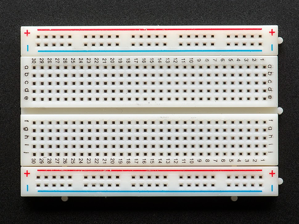
Figure 9: This is a breadboard. The breadboard helped us connect our circuit all together.
5/6 - 5/13
Week 5
Throughout the lab period this week, the group continued to talk about some designs. As all the pieces we ordered started to come in, our minds were better able to wrap around the idea that we have come up with. Getting the materials made it much easier for us to visualize the device. We are still waiting on a couple more materials for out overall device to come in. However, the ring that we built last week was a big step for us, and using it for our source of light. The only issue that we have come across is that we aren't sure how to make the light sensor and the touch sensor work together yet. This is something we plan to learn, and explore over the next week or so.
Outside of the lab in between weeks 5 and 6, we met together to discuss the building of the device. Because the device is so small, we believe it to be very difficult for all four of us to work on it at a time. This led to the discussion of "who knows what?" What we mean by this, is who is most familiar with this kind of work, as well as who is eager to learn about it. We all were interested in the building, but it seems that some of us will be better suited then others. Also outside of the lab, the group continued to work on the lab notebook, as well as do the 3D AutoCAD models of the design.
Outside of the lab in between weeks 5 and 6, we met together to discuss the building of the device. Because the device is so small, we believe it to be very difficult for all four of us to work on it at a time. This led to the discussion of "who knows what?" What we mean by this, is who is most familiar with this kind of work, as well as who is eager to learn about it. We all were interested in the building, but it seems that some of us will be better suited then others. Also outside of the lab, the group continued to work on the lab notebook, as well as do the 3D AutoCAD models of the design.
4/29 - 5/6
Week 4
This week in lab, the group discussed many things that we must accomplish over the next couple weeks. This included many things like money that we need to spend, timing for things that need completed, and many other various things that relate to the overall task. We also did some research on how to wire LED lights with circuitry. Another thing we began to research was the way that we are going to make the touch sensor work. Also, in the lab, the an issue was brought up by the instructor, that would make our device more versatile. He brought up something that would also help to let the person know they are at the right section of the keyboard when typing. This is an issue we had given little thought to before, however, now realize it to be more of an issue. We have come up with a possible resolution that would have another LED light, that when the device came in contact with a designated key the device would light up.
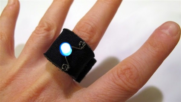
Outside of lab, the group built a device that would be a possible start to our final project. It is a ring with an LED light on it. This is shown in Figure 8.
Figure 8: This in a Azellaco etextile LED ring kit that our team leader assembled. This is a simple LED setup that has a circuit board, and is connected by conductive thread. This is a possible option for what we will attempt to build off of.
4/22 - 4/29
Week 3
Outside of class lading up to the lab, the group finished the preliminary design brief. This took quite bit of time and consideration to complete. The brief went into full detail about the design of the device, and what technical issues we will come across as well as the overall cost of the pieces in the device.
Through this week, in class we presented our projects to the class, and answered questions based on the project. We discussed many issues that could arise throughout the whole process of the project. Also found some statistics to prove how many people suffer from the disease that we are targeting the device towards. The class offered us some very helpful tips on how to build our device. One kid even mentioned a possible touch sensor that we could use. Also in the lab, we wrote system block diagrams that explain the overall process of the design, and the outcomes of the design. This is shown in Figure 7.
.jpg) |
| Figure 7: System Block Diagram. In class, we came up with a block diagram that describes all of the inputs, outputs, and inner components of the device. |
Outside of class prior to the lab, the group got together and purchased all of the components for the project. This didn't take much time, and it did not cost too much. We purchased a bunch of different pieces, that could lead to a couple different objects for the overall project. We are gonna take these pieces and possibly make a couple different devices. We purchased a bunch of individual lights that we may be able to use for this device as shown in Figure 2. Also we bought velcro straps that will help hook the device onto peoples hands shown in Figure 3. In Figure 4, we show a light that has LED's to see how the circuit board works. In Figure 5, we purchased this one finger fishing glove as the possible harness for the lights and sensor, as it will be comfortable for those who wear the device. Figure 6 is an led ring, that we will attempt to use and wire it into the sensor.
 |
| Figure 6: LED Ring |
 |
| Figure 4: LED Flashlight |
 |
| Figure 5: One Finger Fishing Glove |
 |
| Figure 3: Velcro Straps |
 |
| Figure 2: LED Light |
4/15 - 4-22
Week 2
We met up outside of class to go over the Group Design Exercise. This exercise was to help us understand better what we needed to accomplish, as well as all the criterion for this project.
Today in lab, the group began researching many different options to begin building, and designing the overall device. The main thing we researched was to see if there was already a device that would accomplish the goal we had proposed. So far, we have not found a device that directly corresponds with our device idea. Individually, each one of the group members looked up different ways that this could be built. We googled many different pieces that could influence the way we design the overall unit. Another thing we tackled as a team this week was to begin working on the design proposal. Considering that the proposal is due this upcoming week, we began to start working on the outline. We had to define the problem as well as come up with solutions.
4/8 - 4/15
Week 1
At the beginning of the week 1 lab, this was just starting out so the first thing was to form groups. After the formation of groups the whole class engaged in an activity that had the intent was to show the ideals of teamwork, which it successfully did. The video focused on a wide variety of engineers and designers that were coming up with ideas to help fire safety in populated cities. This helped the students to understand how to work in a team, come up with a variety of ideas, as well as to not discriminate against any different ideas.
Today in lab we formed our groups and brainstormed potential design ideas. Coming to class with ideas already in mind, we investigated a solution to errors while typing for those with nerve damage or burns in their fingers. Our first idea that solved this problem included a finger sleeve that had a pressure sensor on the finger tip. When enough pressure was applied to the sensor a small LED on the sleeve would light up, thus indicating that a button or key was pressed.
The following image is a preliminary sketch of a potential solution to this problem. You can see this preliminary design in Figure 1.
.jpg) |
| Figure 1: Preliminary Design. This overall drawling may not be much, but it is the first design we came up with. This design is a two strap system that has a light, and a cap with a touch sensor on it. |
4/1 to 4/8
No comments:
Post a Comment